Starting from a baseline, not a blank page
The course didn't start with an open brief. The professor issued a baseline pump design as the starting point for every team, which meant the real design work wasn't inventing a rotary vane pump from scratch: it was figuring out where that baseline would actually fail in practice and reworking it until it could. Our group's CAD package is that reworked version: the same fundamental mechanism, redesigned against a specific set of production parameters (target production volume, the fluid it would actually be pumping, and the application it was meant to serve) using design-for-manufacturability (DFM) principles rather than treating manufacturability as an afterthought once the geometry looked right.
That distinction matters more than it sounds. A design that works in a CAD assembly and a design that a shop can actually produce at volume, at cost, with parts that fit every time, are two different problems. Moving from the baseline to a production-viable version meant revisiting tolerances, fits, and material choices with an eye on process capability: not just "can this be machined once," but "can this be made repeatably, the way an actual manufacturing line would make it."
How the mechanism displaces fluid
A rotary vane pump moves fluid without any check valves or reciprocating pistons: a rotor spins off-center inside a circular housing, and a set of vanes slide in and out of slots in the rotor as it turns, staying in contact with the housing wall under spring or centrifugal loading. As the rotor turns, the volume trapped between each pair of vanes grows on the intake side and shrinks on the discharge side: the geometry alone does the pumping.
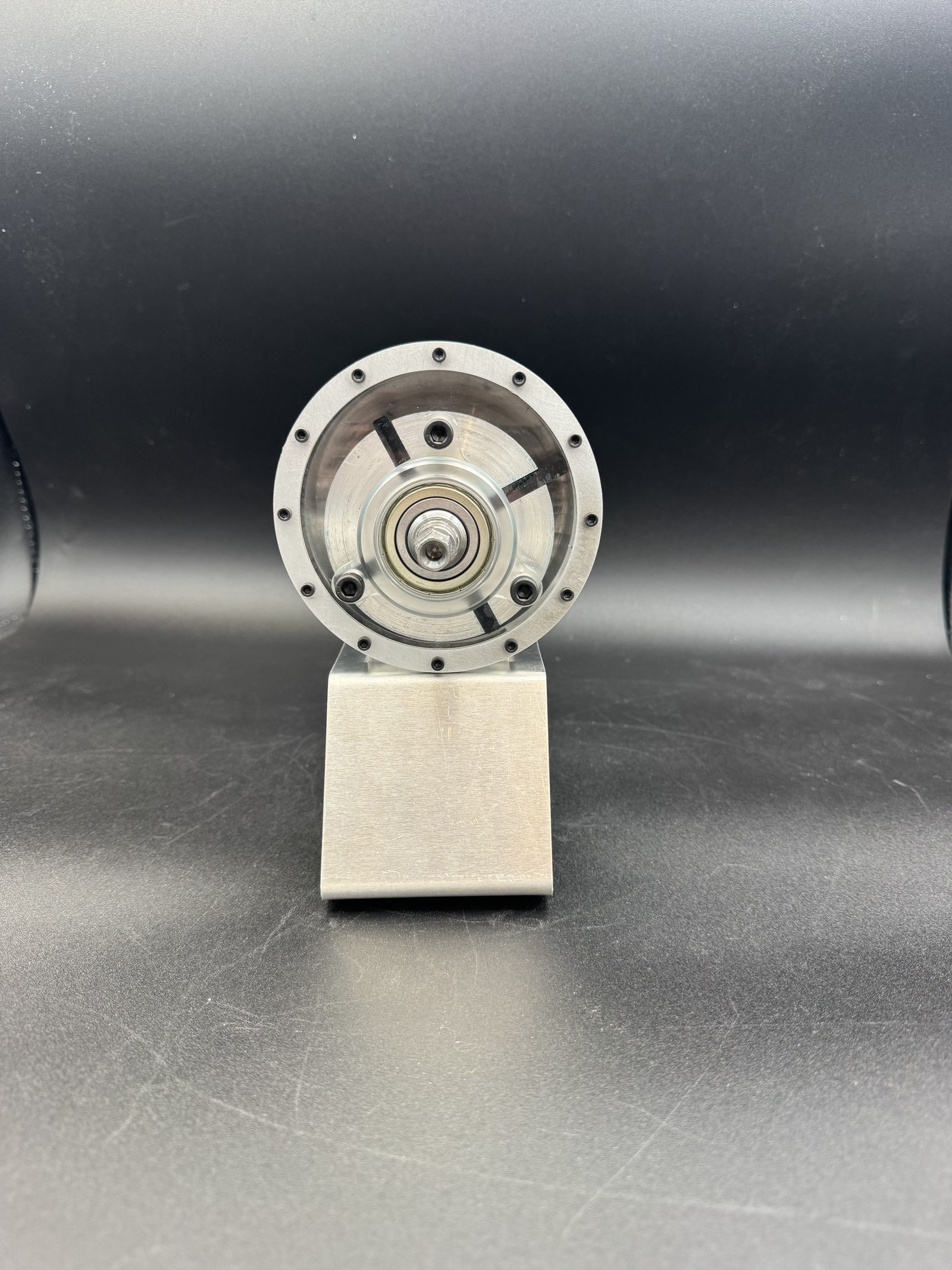
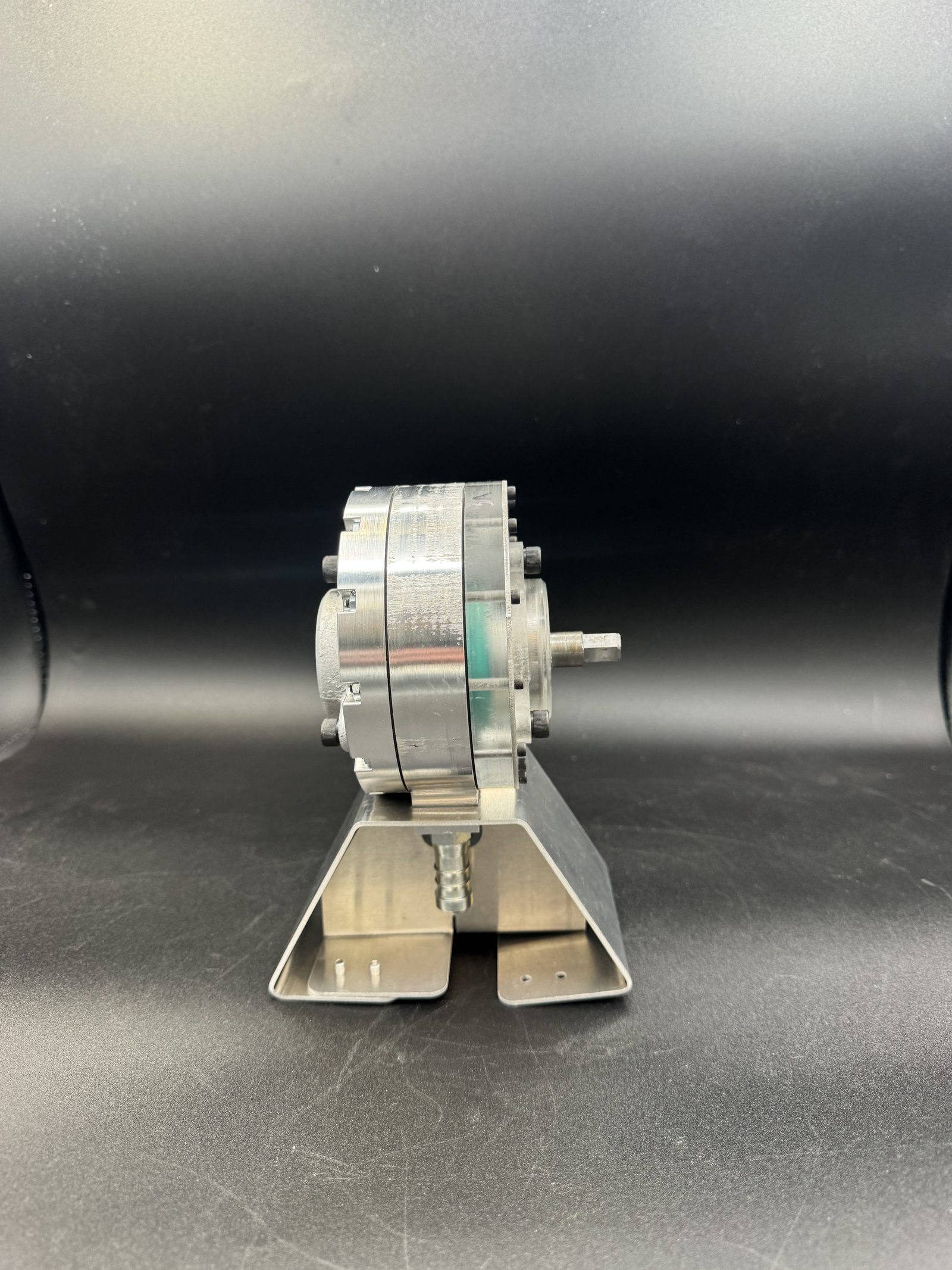
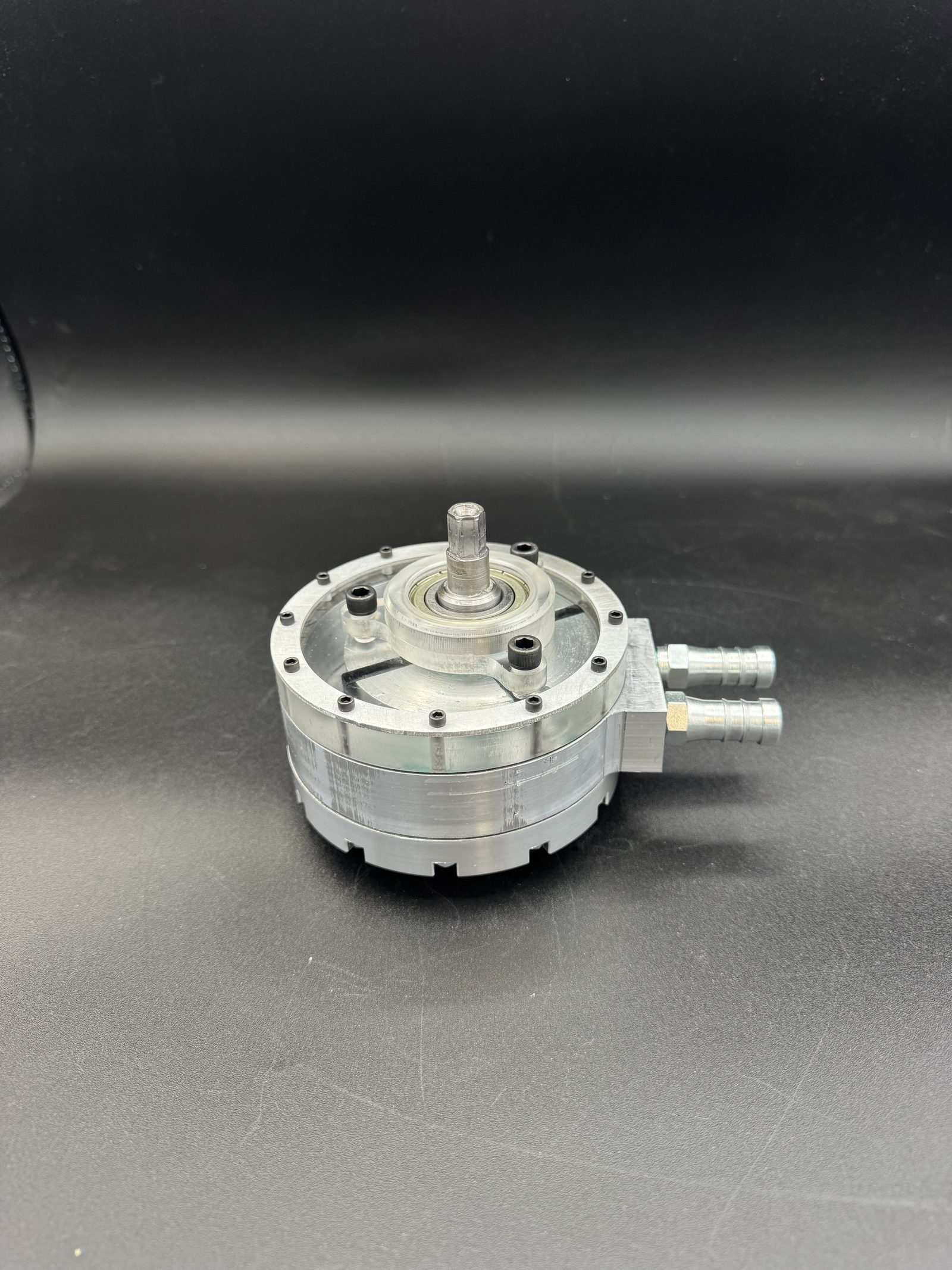
The housing is fully enclosed, so the vane geometry that actually does the pumping isn't visible from outside. Here's the mechanism the assembly above is hiding:
Where the difficulty actually lives
The working principle is simple to sketch and hard to build. Pump efficiency and reliability come down to a small number of tight clearances: the gap between vane tip and housing wall has to be small enough to seal against leak-back, but not so small that the vane binds or gouges the housing as it slides. That's a tolerancing and material problem as much as a geometry problem, and it's why the design work went well beyond the initial concept sketch: into vane slot clearance, rotor eccentricity, and how the housing bore was going to be finished.
The drawing package
A 19-part assembly like this doesn't get built off a single model: it gets built off a released drawing package, where every fit, thread, and surface is called out explicitly enough that a machinist who never saw the CAD could still make the part correctly. Across the package I reviewed and approved GD&T on the individual part drawings, and authored the sub-assembly sheets myself, including the written assembly procedures below, down to specifics like heating the rotor to 700°F and cooling the shaft to 32°F for a shrink-fit press assembly. Click any sheet to view it at full resolution.
From CAD to hardware
The pump was modeled in OnShape, with the rotor, housing, and vane geometry parameterized so eccentricity and vane count could be adjusted without rebuilding the model from scratch, useful for iterating on the displacement-per-revolution before committing to fabrication. On the shop floor, the components came off a mix of processes: CNC and manual milling, a manual lathe, and sand casting, depending on what each part actually needed rather than defaulting to one method for everything.